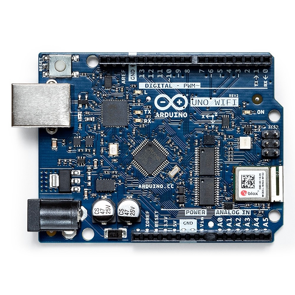

The revision 3 board changes the 8 pin connector that contains Arduino pins 8 to 13, GND and AREF for a 10 pin connector.

This is the spare op-amp that was unused on previous boards. The revision 3 board buffers this LED/resistor through a unity gain op-amp.

The Arduino Uno and Arduino Uno revision 2 both have a LED and resistor connected in series on Arduino pin 13. DTR (HWB) Lineīoth revision 2 and 3 boards add a 1k pull-down resistor to the DTR (HWB) line coming from the USB ATMEGA microcontroller – from the PD7 pin.Īs an Amazon Associate I earn from qualifying purchases: On-Board "L" LED Revision 2 and 3 boards are both supplied with header pins in the USB ATMEGA ICSP header rather than just solder pads in the Arduino Uno. Revision 3 adds a diode across the USB ATMEGA reset pin pull-up resistor. The Arduino Uno and Arduino Uno revision 2 both have an ATMEGA8U2 USB microcontroller on board – this is upgraded to an ATMEGA16U2 on the revision 3 board. Solder Padsīoth revision 2 and 3 boards add four solder pads (JP2) connecting to pins PB4 to PB7 of the USB ATMEGA. This is changed back to square position on the revision 3 board. On the Arduino Uno revision 2 board, the ATMEGA8U2 is positioned at 45 degrees.


 0 kommentar(er)
